


DirectX RayTracing (3) 程序圖元及複雜光照
離上一篇文章隔的有點久了,在國慶前其實就看完了微軟官方的案例並復刻了出來,但是一直懶得寫,國慶也全拿去玩了,拖到過完了國慶才動筆。
在前面兩篇中基本把 DXR 的大部分流程都介紹完了,這次把使用 Intersection Shader 實現程序圖元介紹完後基本足夠實現大部分需求了。在實現程序圖元之前,這裏先實現複雜場景的渲染,將上次的單物體渲染擴展為多物體,同時實現貼圖和陰影的渲染。
光追管線的佈局定義
在創建光追管線之前,需要對光追管線使用的各種結構體及部分參數進行定義,這裏我將所有的參數都放在了一個頭文件中,並使用預處理指令來區分是在 C++ 中還是在 HLSL 中,一邊兩者都可包含此頭文件:
// 用於區分在C++代碼包含還是被HLSL代碼包含

#if defined(__cplusplus)
using float2 = std::pair<float, float>;
using float3 = DSM::Math::Vector3;
using float4 = DSM::Math::Vector4;
using float3x3 = DSM::Math::Matrix3;
using float4x4 = DSM::Math::Matrix4;
using uint = uint32_t;
#endif


#define MAX_TRACE_RECURSION_DEPTH 3


struct MaterialConstantBuffer
{
    float4 baseColor;
    float4 emissiveColor;
    float normalTexScale;
    float metallicFactor;
    float roughnessFactor;
    float pad;
};

struct DirectionalLightData
{
    float4 color;
    float4 direction;
};

struct LightData
{
    uint dirLightCount;
};

namespace RayTracing {
    struct Ray
    {
        float3 origin;
        float3 direction;
    };

    struct RayPayload
    {
        float4 color;
        uint depth;
    };

    struct ShadowRayPayload
    {
        bool visible;
    };

    // 自定義圖元的屬性
    struct ProceduralPrimitiveAttributes
    {
        float3 normal;
        float2 uv;
        bool frontFace;
    };

    // 場景的常量緩衝區
    struct SceneConstantBuffer
    {
        // 生成光線使用的數據
        float4 cameraPosAndFocusDist;
        float4 viewportU;
        float4 viewportV;
    };

    struct PrimitiveInstanceConstantBuffer
    {
        uint primitiveType; // 圖元類型
    };

    // 使用的光線種類
    enum RayType{
        Radiance = 0,
        Shadow,
        Count
    };

    namespace TraceRayParameters {
        // 實例掩碼
        static const uint InstanceMark = ~0;
        namespace HitGroup {
            static const uint Offset[RayType::Count] = {
                0,   // 用於渲染的光線
                1    // 用於陰影的光線
            };
            static const uint GeometryStride = RayType::Count;
        }

        namespace MissShader {
            // Miss Shader 只需要使用索引
            static const uint Offset[RayType::Count] = {
                0,   // 用於渲染的光線
                1    // 用於陰影的光線
            };
        }
    }

    // 解析幾何的類型
    namespace AnalyticPrimitive{
        enum PrimitiveType{
            Sphere = 0,
            Quad,
            Cube,
            Count
        };
    }


}
在命名空間 RayTracing 外的結構體都是使用在後續綁定到管線中的常量緩衝區,命名空間內定義了兩個光追負載,分別是RayPayload和ShadowRayPayload,兩者分別用於場景光照的渲染及陰影的渲染。光照的渲染和陰影的渲染由於邏輯不同,需要使用兩種不同的 Ray 來進行渲染,因此使用了枚舉RayType來區分兩種不同的光線。而後面命名空間TraceRayParameters內的靜態變量為調用TraceRay時使用的參數,這裏順帶在複習一下TraceRay的參數:
Template<payload_t>
void TraceRay(RaytracingAccelerationStructure AccelerationStructure,
              uint RayFlags,
              uint InstanceInclusionMask,
              uint RayContributionToHitGroupIndex,
              uint MultiplierForGeometryContributionToHitGroupIndex,
              uint Miss ShaderIndex,
              RayDesc Ray,
              inout payload_t Payload);
其中第三個參數InstanceInclusionMask就使用TraceRayParameters::InstanceMark進行填寫,在光線遍歷加速結構的時候就會使用該掩碼來判斷是否要跳過該節點;第四個參數RayContributionToHitGroupIndex使用TraceRayParameters::HitGroup::Offset來填寫,表示當前光線使用的 Hit Group 在所有光線類型的 Shader Record 中的偏移,也就是當前類型的光線在所有光線類型的索引,若是不清楚的可以在第一篇中的 Shader Table 那一節詳細瞭解;第五個參數為每個幾何體使用的光線類型,使用TraceRayParameters::HitGroup::GeometryStride進行填寫;第六個參數為在 Miss Shader Table 中的索引,渲染光照與渲染陰影使用的 Miss Shader 各不相同,因此TraceRayParameters::MissShader::Offset進行區分。在調用的時候可直接通過一下方式調用,提高了可讀性:
TraceRay(gScene,
    RAY_FLAG_CULL_BACK_FACING_TRIANGLES,
    RayTracing::TraceRayParameters::InstanceMark,
    RayTracing::TraceRayParameters::HitGroup::Offset[RayTracing::RayType::Radiance],
    RayTracing::TraceRayParameters::HitGroup::GeometryStride,
    RayTracing::TraceRayParameters::MissShader::Offset[RayTracing::RayType::Radiance],
    rayDesc,
    payload);
此外還有後面會用到的結構體,就不詳細介紹了。
加速結構的創建
加載模型
模型的加載這裏使用了 assimp 庫,紋理加載使用了 stbimage 和 DDSTextureLoader12,具體的實現就不介紹了,詳細可見 GitHub 上的項目源碼,鏈接在文末。這裏就簡單介紹一下加載後得到的結構體,模型結構體如下:
struct Model
{
    std::string name{};
    DirectX::BoundingBox boundingBox{};
    std::vector<std::shared_ptr<Mesh>> meshes{};
    std::vector<std::shared_ptr<Material>> materials{};
    std::vector<TextureRef> textures{};
    GpuBuffer materialData{};

    Transform transform{};
};
其中 Mesh 保存了所有幾何體的頂點和索引數據,詳細如下:
enum PSOFlags : std::uint16_t
{
    kHasPosition = ( 1 << 0 ),
    kHasNormal = ( 1 << 1 ),
    kHasTangent = ( 1 << 2 ),
    kHasUV = ( 1 << 3 ),
    kAlphaBlend = ( 1 << 4 ),
    kAlphaTest = ( 1 << 5 ),
    kBothSide = ( 1 << 6 ),
};

struct Mesh
{
    std::string m_Name;

    DirectX::BoundingBox m_BoundingBox;
    // 設置頂點緩衝區使用的數據
    D3D12_VERTEX_BUFFER_VIEW m_PositionStream;
    D3D12_VERTEX_BUFFER_VIEW m_NormalStream;
    D3D12_VERTEX_BUFFER_VIEW m_UVStream;
    D3D12_VERTEX_BUFFER_VIEW m_TangentStream;
    // 索引緩衝區使用的數據
    D3D12_INDEX_BUFFER_VIEW m_IndexBufferViews;
    // 為 PSOFlags 用於判斷是否有各個頂點數據
    uint16_t m_PSOFlags;
    // 暫時無用
    uint16_t m_PSOIndex;

    // 每次繪製需要使用的數據
    struct SubMesh
    {
        uint32_t m_IndexCount;
        uint32_t m_IndexOffset;
        uint32_t m_VertexCount;
        uint32_t m_VertexOffset;
        uint16_t m_MaterialIndex;
        // 使用的紋理在描述符堆中的偏移
        uint16_t m_SRVTableOffset;
    };
    std::map<std::string, SubMesh> m_SubMeshes;

    GpuBuffer m_MeshData{};
};
所有的頂點數據都上載到顯存中,儲存在 m_MeshData 裏,其中 m_PositionStream 後續會在創建頂層加速結構中使用,剩下的 normal、uv、index 會在渲染的時候作為 StructuredBuffer 綁定到局部根簽名中。網格使用的紋理對應的 SRV 在加載模型的時候就創建在了描述符堆中,儲存在 Renderer::m_TextureHeap中,在每一個 SubMesh 中保存了在 Heap 中的索引。在改例子中我使用 PBR 渲染場景中的物體,因此模型中保存材質的定義如下:
enum MaterialTex
{
    kBaseColor, kDiffuseRoughness, kMetalness, kOcclusion, kEmissive, kNormal, kNumTextures
};

struct Material
{
    Math::Vector4 baseColor = {1,1,1,1};
    Math::Vector4 emissiveColor = {0,0,0,0};
    float normalTexScale = 1;
    float metallicFactor = 1;
    float roughnessFactor = 1;
};
由於該文章主要介紹的是 DXR,因此有關 PBR 渲染後面只會簡單提一下。
創建底層加速結構
在創建加速結構之前還需要定義一個輔助類,包含了加速結構本身、暫存緩衝區、加速結構的大小以及只有頂層加速結構會使用的實例描述,其定義如下:
struct AccelerationStructureBuffers
{
    GpuBuffer scratch;
    GpuBuffer accelerationStructure;
    GpuBuffer instanceDesc;    // Used only for top-level AS
    uint64_t resultDataMaxSizeInBytes;
};
在先前的例子中之使用了一個底層加速結構,而頂層加速結構的創建又依賴於底層加速結構,因此可以共用一個暫存緩衝區。但是現在需要同時創建多個底層加速結構,因此每個底層加速結構都需要單獨使用暫存緩存區。在這裏我先創建一個光線追蹤類來儲存管線中需要的資源與實現資源創建,其定義如下:
class RayTracer
{
public:
    RayTracer();

    void SetCamera(const Camera* camera) { m_Camera = camera; }
    void TraceRays(ComputeCommandList& cmdList);

    void AddModel(std::shared_ptr<Model> model);
    void AddProceduralGeometry(const ProceduralGeometryDesc& desc);
    void AddLight(const Light& light);

private:
    void CreateAccelerationStructure();
    void CreateShaderTable();

public:
    static constexpr size_t sm_MaxDirLightCount = 4;

private:
    const Camera* m_Camera;

    std::vector<std::shared_ptr<Model>> m_Models;
    std::unique_ptr<ProceduralGeometryManager> m_ProceduralGeometryManager;

    // 加速結構
    std::vector<AccelerationStructureBuffers> m_BottomLevelASs{};
    AccelerationStructureBuffers m_TopLevelAS{};

    // 着色器表
    GpuBuffer m_RayGenShaderTable{};
    GpuBuffer m_MissShaderTable{};
    GpuBuffer m_HitShaderTable{};


    // 光照信息
    GpuBuffer m_LightDataBuffer;
    GpuBuffer m_DirLightDataBuffer;
    std::vector<DirectionalLightData> m_DirLights{};
};
每次調用AddModel的時候都會調用CreateAccelerationStructure重新生成加速結構,這裏暫不考慮效率問題,因此每次都會重新生成所有的底層加速結構。對於創建底層加速結構,在第一篇文章已經做了詳細的介紹,這裏再複習一下。底層加速結構的創建可分為以下幾個步驟:
-
填寫
D3D12_RAYTRACING_GEOMETRY_DESC結構體,由於使用的模型都是三角網格,因此類型填寫為三角形,順帶提一下光追管線中三角形的圖元類型只有三角形列表,不支持三角形帶(Triangle Strips),具體代碼如下:// 給底層加速結構的幾何描述 D3D12_RAYTRACING_GEOMETRY_TRIANGLES_DESC trianglesDesc{}; trianglesDesc.Transform3x4 = 0; trianglesDesc.IndexFormat = DXGI_FORMAT_R32_UINT; trianglesDesc.VertexFormat = DXGI_FORMAT_R32G32B32_FLOAT; trianglesDesc.IndexCount = submesh.m_IndexCount; trianglesDesc.VertexCount = submesh.m_VertexCount; trianglesDesc.IndexBuffer = mesh->m_IndexBufferViews.BufferLocation + submesh.m_IndexOffset * sizeof(uint32_t); trianglesDesc.VertexBuffer.StartAddress = mesh->m_PositionStream.BufferLocation + submesh.m_VertexOffset * mesh->m_PositionStream.StrideInBytes; trianglesDesc.VertexBuffer.StrideInBytes = mesh->m_PositionStream.StrideInBytes; D3D12_RAYTRACING_GEOMETRY_DESC geometryDesc{}; geometryDesc.Type = D3D12_RAYTRACING_GEOMETRY_TYPE_TRIANGLES; geometryDesc.Flags = D3D12_RAYTRACING_GEOMETRY_FLAG_OPAQUE; geometryDesc.Triangles = trianglesDesc;這裏填入模型的頂點數據及索引數據的時候使用了模型類中的 VBV 和 IBV,使用內部的 BufferLocation 及 StrideInBytes 來將對應數據的 GPU虛擬地址傳給結構體。在描述三角形網格的結構體中有一個參數為
Transform3x4,對於該參數有兩點需要注意,一是該變量與頂層加速結構使用的D3D12_RAYTRACING_INSTANCE_DESC中的Transform並不相同,雖然兩者都是對底層加速結構進行變換,但是該參數是將該矩陣變換應用到所有的頂點上,因此若是使用該參數會增加構造底層加速結構的開銷;二是雖然該參數需要填寫的變換矩陣對應的 GPU 地址,但是在構造完底層加速結構之後改變該地址內的變換矩陣並不會對已經生成的底層加速結構產生影響,因此就別想着通過該參數減少加速結構的構建了,若是想要對幾何體進行變換,還是需要重新構建加速結構。 -
填寫完幾何描述之後就需要填寫
D3D12_BUILD_RAYTRACING_ACCELERATION_STRUCTURE_INPUTS結構體,具體操作與之前相同。 -
隨後就是獲取構建加速結構所需要的信息,同時為加速結構及要使用的暫存緩衝區分配顯存,具體操作與之前相同,只不過將 Buffer 儲存在前面提到的
AccelerationStructureBuffers結構體中。這裏也有兩點需要注意,一是兩個 Buffer 需要允許隨機訪問,也就是有D3D12_RESOURCE_FLAG_ALLOW_UNORDERED_ACCESS標識;二是加速結構的資源狀態需要為D3D12_RESOURCE_STATE_RAYTRACING_ACCELERATION_STRUCTURE。 -
最後就是使用命令隊列構造加速結構了,注意這裏需要為底層加速結構保存一個 UAV Barrier,但是也不要馬上提交了,不然每次都等待加速結構創建完效率很低,一般 Barrier 的數量達到16個再提交比較好,再多的話對性能也不是很好:
D3D12_BUILD_RAYTRACING_ACCELERATION_STRUCTURE_DESC buildBottomLevelASDesc{}; buildBottomLevelASDesc.Inputs = bottomLevelASInputs; buildBottomLevelASDesc.ScratchAccelerationStructureData = bottomLevelBuffers.scratch.GetGpuVirtualAddress(); buildBottomLevelASDesc.DestAccelerationStructureData = bottomLevelBuffers.accelerationStructure.GetGpuVirtualAddress(); cmdList.GetDXRCommandList()->BuildRaytracingAccelerationStructure(&buildBottomLevelASDesc, 0, nullptr); // 等待底層加速結構構建完畢 cmdList.InsertUAVBarrier(bottomLevelBuffers.accelerationStructure);InsertUAVBarrier的實現如下:void CommandList::InsertUAVBarrier(GpuResource& resource, bool flush) // 默認 false { D3D12_RESOURCE_BARRIER resourceBarrier = {}; resourceBarrier.Type = D3D12_RESOURCE_BARRIER_TYPE_UAV; resourceBarrier.UAV.pResource = resource.GetResource(); resourceBarrier.Flags = D3D12_RESOURCE_BARRIER_FLAG_NONE; m_ResourceBarriers.push_back(std::move(resourceBarrier)); if (m_ResourceBarriers.size() >= 16 || flush) { FlushResourceBarriers(); } } void CommandList::FlushResourceBarriers() { if (!m_ResourceBarriers.empty()) { m_CmdList->ResourceBarrier(m_ResourceBarriers.size(), m_ResourceBarriers.data()); } m_ResourceBarriers.clear(); }
遍歷所有模型中的 Mesh 及 Mesh 中的 SubMesh,並執行加速結構的創建,這樣就得到了場景中所有物體的底層加速結構。
創建頂層加速結構
頂層加速結構的創建也與之前相同,唯一的區別是D3D12_RAYTRACING_INSTANCE_DESC有多個,在遍歷模型的時候需要順帶在創建完底層加速結構之後填寫該結構體,相比之前創建的 Instance,這次創建是需要填寫InstanceContributionToHitGroupIndex參數,在第一篇文章中也提到過,該參數表示當前底層加速結構的 Shader Record 在 Shader Table 中的偏移量,在調用TraceRay後光追管線會通過該參數及上面提到的TraceRay中的參數來索引需要使用的 Shader Record。具體操作如下:
uint32_t instanceContributionToHitGroupIndex = 0;
std::vector<D3D12_RAYTRACING_INSTANCE_DESC> instanceDescs;
for(const auto& model : m_Models){
    for(const auto& mesh : model->meshes){
        for(const auto& submesh : mesh->m_SubMeshes){
            Build Acceleration Structure
            ...

            // 頂層加速結構的輸入,使用底層加速結構作為輸入
            D3D12_RAYTRACING_INSTANCE_DESC instanceDesc{};
            instanceDesc.InstanceMask = RayTracing::TraceRayParameters::InstanceMark;
            instanceDesc.InstanceContributionToHitGroupIndex = instanceContributionToHitGroupIndex;
            instanceDesc.AccelerationStructure = bottomLevelBuffers.accelerationStructure.GetGpuVirtualAddress();
            DirectX::XMStoreFloat3x4(&reinterpret_cast<DirectX::XMFLOAT3X4&>(instanceDesc.Transform), model->transform.GetLocalToWorld());
            instanceDescs.push_back(std::move(instanceDesc));
            instanceContributionToHitGroupIndex += bottomLevelASInputs.NumDescs * RayTracing::RayType::Count;
        }
    }
}
每次創建底層加速結構,偏移量就會加上光線的類型數量。
創建 Shader Table
先前創建的 Shader Table 都只包含一個 Shader Record,同時局部根簽名也較為簡單,只有一個根常量。而這次使用的局部根簽名還包含了物體的材質、紋理,以及幾何數據,在第二篇文章中由於只有一個物體,因此我將法線等幾何數據放在全局根簽名中,但是這次每個物體都有各自的幾何數據,因此放在局部根簽名中較為方便。在由於 Shader Table 需要使用局部根簽名,因此這裏先定義一下管線需要使用到的根簽名。
根簽名的佈局及創建
在這次的例子中,需要定義一個全局根簽名與兩個局部根簽名,兩個局部根簽名分別給三角圖元和自定義圖元使用。這裏使用枚舉來定義各個根參數所對應的根索引,提高可讀性。全局根簽名的佈局如下:
// 根簽名的佈局
namespace GlobalRootSignature {
    namespace RayTracing{
        enum Slot {
            RayTracingOutput = 0,
            AccelerationStructure,
            SceneConstantBuffer,
            Count
        };
    }

    namespace Light{
        enum Slot {
            LightData = RayTracing::Slot::Count,
            DirectionalLightDatas,
            Count
        };
    }

    static constexpr uint32_t GlobalRootSignatureCount = Light::Slot::Count;

    namespace StaticSampler {
        enum Slot {
            AnisoWrap = 0,
            Count
        };
    }
}
命名空間GlobalRootSignature內包含了三個命名空間,分別表示光追需要使用的資源、光照需要使用的資源和靜態採樣器,光追的資源與前兩次相同,光照信息中的LightData中包含了方向光的數量,而DirectionalLightDatas後續會綁定一個StructuredBuffer,包含了方向光的數據。
局部根簽名的佈局如下:
// 局部根簽名
namespace LocalRootSignature {
    namespace Type {
        enum Enum {
            Triangle = 0,
            AABB,
            Count
        };
    }

    namespace Triangle {
        enum Slot {
            Material = 0,
            IndexBuffer,
            NormalBuffer,
            UVBuffer,
            Textures,
            Count
        };
        struct RootArguments {
            MaterialConstantBuffer material;
            D3D12_GPU_VIRTUAL_ADDRESS indexBuffer;
            D3D12_GPU_VIRTUAL_ADDRESS normalBuffer;
            D3D12_GPU_VIRTUAL_ADDRESS uvBuffer;
            D3D12_GPU_DESCRIPTOR_HANDLE textures;   // 6 個 PBR 紋理
        };
    };

    namespace AABB{
        enum Slot{
            Material = 0,
            Textures,
            PrimitiveInstance,
            Count
        };
        // 16 字節對齊
        struct RootArguments{	// 16字節對齊,共64字節
            MaterialConstantBuffer material;	// 16字節對齊,共48字節
            D3D12_GPU_DESCRIPTOR_HANDLE textures;   // 6 個 PBR 紋理
            RayTracing::PrimitiveInstanceConstantBuffer primitiveInstance;
        };
    }

    inline uint32_t MaxRootArgumentsSize()
    {
        return (std::max)(sizeof(Triangle::RootArguments), sizeof(AABB::RootArguments));
    }
}
命名空間LocalRootSignature內同樣包含了三個命名空間,分別表示命名空間的數量、三角形圖元及 AABB 盒需要使用的局部根簽名及對應的結構體,這裏提一下 DXR 的自定義圖元統一使用 AABB 盒進行表示,在創建底層加速結構的時候會定義其對應的** AABB 盒**,同時在調用TraceRay之後光線會先與該圖元的 AABB 盒進行相交檢測,判斷相交後才會在 Shader Table 中索引其對應的的 Shader Record 並調用內部的 Hit Group 的 Intersection Shader 來判斷是否相交,詳細操作後面會提到。
除了使用枚舉來定義各個根參數的索引外,上面還定義了各個局部根簽名所使用的結構體,這裏以三角圖元的為例説明不同的根參數需要使用什麼來進行綁定。
- 第一個參數
MaterialConstantBuffer使用根常量來描述,因此直接使用描述材質的結構體即可。 - 第二到四個參數為物體的幾何信息,使用 SRV 也就是描述符綁定到管線中,需要使用 GPU 的虛擬地址,也就是
D3D12_GPU_VIRTUAL_ADDRESS進行綁定。CBV 和 UAV 同理。 - 第五個參數為物體使用的紋理,使用描述符表綁定到管線中,使用的是首個描述符在描述符堆中的 GPU 句柄進行綁定。
而 AABB 的三個成員分別使用根常量、描述符表、根常量來描述。這裏需要注意各個成員參數的順序需要與聲明根簽名時對應的根索引相同。在最後還有一個MaxRootArgumentsSize函數,返回兩個根簽名對應的結構體佔用的最大大小,這是由於 Shader Table 中的每一 Shader Record 大小需要相同,且大小為最大的那個 Shader Record 的大小。
在定義這些結構體的時候有一點特別要注意,那就是結構體的對齊,例如上面的結構體AABB::RootArguments,若是我把裏面的參數交換一下就會導致映射到 GPU 的數據發生錯誤,原因是我的MaterialConstantBuffer使用了 DirectX Math 的DirectX::XMVECTOR,導致其是16字節對齊,因此現在該結構體的內存佈局如下:
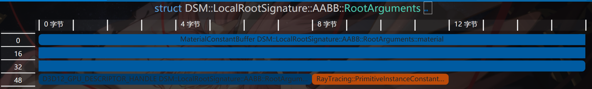
而我一開始的順序卻不是這樣的:
struct PrimitiveInstanceConstantBuffer{	// 4字節
    uint primitiveType; // 圖元類型
};

struct RootArguments{	// 16字節對齊,共80字節
    RayTracing::PrimitiveInstanceConstantBuffer primitiveInstance;	// 4字節
    MaterialConstantBuffer material;	// 16字節對齊,共48字節
    D3D12_GPU_DESCRIPTOR_HANDLE textures;   // 6 個 PBR 紋理,8字節
}
可以看到這時候多了16字節,都用於對齊內存,現在的內存佈局如下:
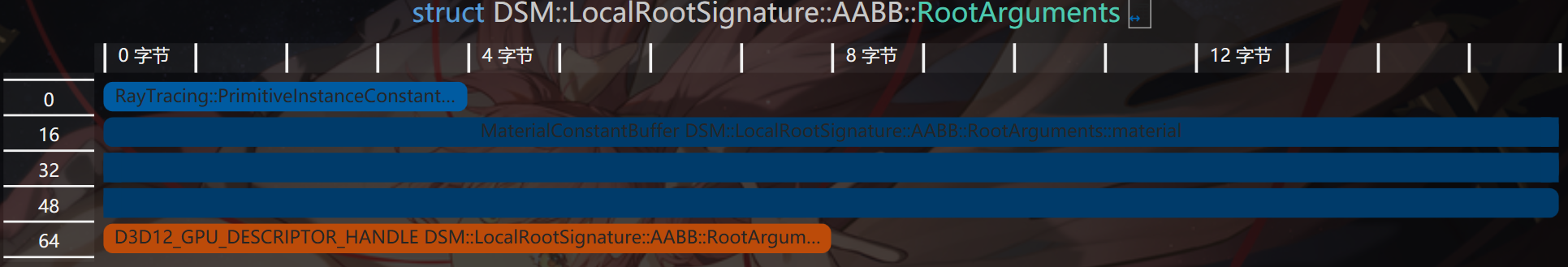
可以看到primitiveInstance變量後面的12字節全用來對齊了,但是在我是使用根常量來描述該變量,因此管線會將4字節開始的內存視為下一個根參數的起點,但實際上並不是,這就會導致綁定的資源錯誤。
定義完佈局之後根據佈局及 HLSL 中各個資源對應的寄存器槽創建根簽名即可:
auto& triangleRootSig = m_LocalRootSigs[LocalRootSignature::Type::Triangle];
auto& aabbRootSig = m_LocalRootSigs[LocalRootSignature::Type::AABB];
triangleRootSig[LocalRootSignature::Triangle::Slot::Material].InitAsConstants(1, Math::AlignUp(sizeof(MaterialConstantBuffer), 4) / sizeof(uint32_t));
triangleRootSig[LocalRootSignature::Triangle::Slot::IndexBuffer].InitAsBufferSRV(1);
triangleRootSig[LocalRootSignature::Triangle::Slot::NormalBuffer].InitAsBufferSRV(2);
triangleRootSig[LocalRootSignature::Triangle::Slot::UVBuffer].InitAsBufferSRV(3);
triangleRootSig[LocalRootSignature::Triangle::Slot::Textures].InitAsDescriptorRange(D3D12_DESCRIPTOR_RANGE_TYPE_SRV, 4, kNumTextures);
triangleRootSig.Finalize(L"RayTracingLocalRootSignature_Triangle", D3D12_ROOT_SIGNATURE_FLAG_LOCAL_ROOT_SIGNATURE);

size_t instanceCBSize = Math::AlignUp(sizeof(RayTracing::PrimitiveInstanceConstantBuffer), 4);
aabbRootSig[LocalRootSignature::AABB::Slot::PrimitiveInstance].InitAsConstants(2, instanceCBSize / sizeof(uint32_t));
aabbRootSig[LocalRootSignature::AABB::Slot::Material].InitAsConstants(1, Math::AlignUp(sizeof(MaterialConstantBuffer), 4) / sizeof(uint32_t));
aabbRootSig[LocalRootSignature::AABB::Slot::Textures].InitAsDescriptorRange(D3D12_DESCRIPTOR_RANGE_TYPE_SRV, 4, kNumTextures);
aabbRootSig.Finalize(L"RayTracingLocalRootSignature_AABB", D3D12_ROOT_SIGNATURE_FLAG_LOCAL_ROOT_SIGNATURE);

m_GlobalRootSig[GlobalRootSignature::RayTracing::RayTracingOutput].InitAsDescriptorRange(D3D12_DESCRIPTOR_RANGE_TYPE_UAV, 0, 1);  // RayTracingOutput
m_GlobalRootSig[GlobalRootSignature::RayTracing::AccelerationStructure].InitAsBufferSRV(0);  // 加速結構
m_GlobalRootSig[GlobalRootSignature::RayTracing::SceneConstantBuffer].InitAsConstantBuffer(0);
m_GlobalRootSig[GlobalRootSignature::Light::LightData].InitAsConstantBuffer(0, D3D12_SHADER_VISIBILITY_ALL, 1);
m_GlobalRootSig[GlobalRootSignature::Light::DirectionalLightDatas].InitAsBufferSRV(0, D3D12_SHADER_VISIBILITY_ALL, 1);
        m_GlobalRootSig.InitStaticSampler(GlobalRootSignature::StaticSampler::AnisoWrap, Graphics::SamplerAnisoWrap);
        m_GlobalRootSig.Finalize(L"RayTracingGlobalRootSignature");
創建 Shader Table
創建的步驟與之前相同,部分細節稍有不同,如三角圖元和自定義圖元都有各自的 Shader Identifiers,同時 Miss Shader Record 也有兩個。詳細的操作如下:
// 創建着色器表
// 獲取 Shader 的標識符
Microsoft::WRL::ComPtr<ID3D12StateObjectProperties> stateObjectProps{};
ASSERT_SUCCEEDED(g_Renderer.m_RayTracingStateObject.As(&stateObjectProps));
void* rayGenShaderIdentifier = stateObjectProps->GetShaderIdentifier(Renderer::s_RayGenShaderName);
std::array<void*, RayTracing::RayType::Count> missShaderIdentifiers{};
for (size_t i = 0; i < RayTracing::RayType::Count; i++) {
    missShaderIdentifiers[i] = stateObjectProps->GetShaderIdentifier(Renderer::s_MissShaderName[i]);
}
std::array<void*, RayTracing::RayType::Count> hitGroupIdentifiersTriangle{};
for (size_t i = 0; i < RayTracing::RayType::Count; i++) {
    hitGroupIdentifiersTriangle[i] = stateObjectProps->GetShaderIdentifier(Renderer::s_HitGroupName_Triangle[i]);
}

constexpr uint32_t shaderIdSize = D3D12_SHADER_IDENTIFIER_SIZE_IN_BYTES;

// RayGeneration 着色器表
GpuBufferDesc rayGenShaderTableDesc{};
rayGenShaderTableDesc.m_Size = shaderIdSize;
rayGenShaderTableDesc.m_Stride = rayGenShaderTableDesc.m_Size;
rayGenShaderTableDesc.m_HeapType = D3D12_HEAP_TYPE_DEFAULT;
m_RayGenShaderTable.Create(L"RayGenShaderTable", rayGenShaderTableDesc, rayGenShaderIdentifier);

// Miss 着色器表
constexpr uint32_t missShaderTableSize = shaderIdSize * RayTracing::RayType::Count;
std::array<uint8_t, missShaderTableSize> missShaderTableData{};
for(int i = 0; i < RayTracing::RayType::Count; ++i){
    memcpy(missShaderTableData.data() + i * shaderIdSize, missShaderIdentifiers[i], shaderIdSize);
}
GpuBufferDesc missShaderTableDesc = rayGenShaderTableDesc;
missShaderTableDesc.m_Size = missShaderTableSize;
missShaderTableDesc.m_Stride = shaderIdSize;
m_MissShaderTable.Create(L"MissShaderTable", missShaderTableDesc, missShaderTableData.data());

// Hit 着色器表
uint32_t hitGroupShaderRecordSize = shaderIdSize + LocalRootSignature::MaxRootArgumentsSize();
hitGroupShaderRecordSize = Math::AlignUp(hitGroupShaderRecordSize, D3D12_RAYTRACING_SHADER_RECORD_BYTE_ALIGNMENT);
std::vector<uint8_t> hitGroupShaderTableData{};
std::vector<uint8_t> hitGroupShaderRecordData{};
for (const auto& model : m_Models){
    for(const auto& mesh : model->meshes){
        for(const auto& submesh : mesh->m_SubMeshes) {
            for(int i = 0; i < RayTracing::RayType::Count; i++) {
                hitGroupShaderRecordData.clear();
                // 全部清零以免殘餘數據影響
                hitGroupShaderRecordData.resize(hitGroupShaderRecordSize, 0);
                memcpy(hitGroupShaderRecordData.data(), hitGroupIdentifiersTriangle[i], shaderIdSize);
                if(i == RayTracing::RayType::Radiance){ // 只有渲染光線需要填入根參數
                    LocalRootSignature::Triangle::RootArguments rootArgs{};
                    auto meshMat = model->materials[submesh.m_MaterialIndex];
                    rootArgs.material.baseColor = meshMat->baseColor;
                    rootArgs.material.emissiveColor = meshMat->emissiveColor;
                    rootArgs.material.metallicFactor = meshMat->metallicFactor;
                    rootArgs.material.roughnessFactor = meshMat->roughnessFactor;
                    rootArgs.material.normalTexScale = meshMat->normalTexScale;
                    rootArgs.indexBuffer = mesh->m_IndexBufferViews.BufferLocation + submesh.m_IndexOffset * sizeof(uint32_t);
                    rootArgs.normalBuffer = mesh->m_NormalStream.BufferLocation +
                        submesh.m_VertexOffset * mesh->m_NormalStream.StrideInBytes;
                    rootArgs.uvBuffer = mesh->m_UVStream.BufferLocation +
                        submesh.m_VertexOffset * mesh->m_UVStream.StrideInBytes;
                    rootArgs.textures = g_Renderer.m_TextureHeap[submesh.m_SRVTableOffset];
                    memcpy(hitGroupShaderRecordData.data() + shaderIdSize, &rootArgs, sizeof(rootArgs));
                }
                hitGroupShaderTableData.append_range(hitGroupShaderRecordData);
            }
        }
    }
}

GpuBufferDesc hitShaderTableDesc = rayGenShaderTableDesc;
hitShaderTableDesc.m_Size = Math::AlignUp(hitGroupShaderTableData.size(), D3D12_RAYTRACING_SHADER_TABLE_BYTE_ALIGNMENT);
hitShaderTableDesc.m_Stride = hitGroupShaderRecordSize;
hitGroupShaderTableData.resize(hitShaderTableDesc.m_Size);
m_HitShaderTable.Create(L"HitShaderTable", hitShaderTableDesc, hitGroupShaderTableData.data());
這四個循環做的事其實是遍歷每一個幾何體,為其分配兩個 Shader Record,分別為渲染光照的 Hit Group 和渲染陰影的 Hit Group,陰影的 Hit Group 其實啥也沒有,主要起佔位作用。最後將着色器標識與局部根簽名的參數拷貝到 Shader Record 中。
創建光追管線狀態對象
相比前兩次創建光追的 PSO ,這次需要額外添加與更改幾個參數:
-
需要創建兩個 Hit Group,分別對應兩種光線:
std::array<D3D12_HIT_GROUP_DESC, RayTracing::RayType::Count> hitGroupDescsTriangle{}; for(int i = 0; i < RayTracing::RayType::Count; ++i){ auto& hitGroupDesc = hitGroupDescsTriangle[i]; hitGroupDesc.Type = D3D12_HIT_GROUP_TYPE_TRIANGLES; hitGroupDesc.HitGroupExport = s_HitGroupName_Triangle[i]; if(i == RayTracing::RayType::Radiance){ hitGroupDesc.ClosestHitShaderImport = s_ClosestHitShaderName[GeometryType::Triangle]; } D3D12_STATE_SUBOBJECT hitGroupSubobject{}; hitGroupSubobject.Type = D3D12_STATE_SUBOBJECT_TYPE_HIT_GROUP; hitGroupSubobject.pDesc = &hitGroupDesc; subobjects.push_back(std::move(hitGroupSubobject)); } -
Shader Config 中的光追負載的大小需要為兩種光線負載的最大值,同時由於後續加入的自定義圖元的圖元屬性比內置的圖元屬性大,因此也需要更改:
D3D12_RAYTRACING_SHADER_CONFIG shaderConfig{}; shaderConfig.MaxPayloadSizeInBytes = (std::max)(sizeof(RayTracing::RayPayload), sizeof(RayTracing::ShadowRayPayload)); // 光線的顏色 shaderConfig.MaxAttributeSizeInBytes = sizeof(RayTracing::ProceduralPrimitiveAttributes); // 自定義圖元的法線 -
這次使用了兩個局部根簽名,分別是三角圖元和自定義圖元的,在創建兩個根簽名的子對象的同時還要創建他們與 Hit Group 的關聯。
-
由於添加了陰影光線,因此最大遞歸深度需要大於1:
// Pipeline config
D3D12_RAYTRACING_PIPELINE_CONFIG pipelineConfig{};
pipelineConfig.MaxTraceRecursionDepth = MAX_TRACE_RECURSION_DEPTH;  // 最大遞歸深度,3
創建完 PSO 後 CPU 端的準備工作也就完成了,隨後使用命令列表綁定全局資源與調用DispatchRays即可,流程與之前相同。
編寫 Shader
定義使用的資源
在編寫 Shader 之前還需要定義渲染過程中需要使用的資源,內部使用的結構體在描寫管線佈局的時候已經提到了,可以翻上去看看。以下資源綁定在全局根簽名中,全局都可訪問:
// Global
// 輸出圖像
RWTexture2D<float4> gOutput : register(u0);
// 加速結構
RaytracingAccelerationStructure gScene : register(t0);
ConstantBuffer<RayTracing::SceneConstantBuffer> gSceneCB : register(b0);
以下是描述幾何體材質的資源,綁定在局部根簽名中:
// Common Local
ConstantBuffer<MaterialConstantBuffer> lMaterialCB : register(b1);

Texture2D<float4> lBaseColorTex : register(t4);
Texture2D<float4> lDiffuseRoughnessTex : register(t5);
Texture2D<float4> lMetalnessTex : register(t6);
Texture2D<float> lOcclusionTex : register(t7);
Texture2D<float3> lEmissiveTex : register(t8);
Texture2D<float3> lNormalTex : register(t9);
三角形圖元的才有的幾何數據,同樣綁定在局部根簽名中:
// Triangle Geometry Local
StructuredBuffer<uint3> lIndexBuffer : register(t1);
StructuredBuffer<float3> lNormalBuffer : register(t2);
StructuredBuffer<float2> lUVBuffer : register(t3);
還有程序圖元才有的圖元類型,綁定在程序圖元的局部根簽名中:
// Procedural Geometry Local
ConstantBuffer<RayTracing::PrimitiveInstanceConstantBuffer> lPrimitiveInstanceCB : register(b2);
最後是計算光照使用的光照信息,綁定在全局根簽名中:
ConstantBuffer<LightData> gLightData : register(b0, space1);
StructuredBuffer<DirectionalLightData> gDirLightData : register(t0, space1);
Ray Generation Shader
在該 Shader 要做的工作一樣是生成光線並調用TraceRay,最後將結果寫入 UAV。詳細如下:
[shader("raygeneration")]
void RaygenShader()
{
    RayTracing::Ray ray = GenerateCameraRay(
        DispatchRaysIndex().xy,
        gSceneCB.cameraPosAndFocusDist.xyz,
        gSceneCB.viewportU.xyz,
        gSceneCB.viewportV.xyz,
        gSceneCB.cameraPosAndFocusDist.w);

    float4 color = TraceRadianceRay(ray, 0);

    // 手動進行伽馬映射
    color.rgb = LinearToSRGB(color.rgb);
    gOutput[DispatchRaysIndex().xy] = color;
}
這裏生成光線的部分與第二篇文章相同,而TraceRadianceRay對TraceRay進行了一點封裝添加了最大遞歸深度的限制並返回光追負載中的顏色,每次調用TraceTray,光追負載內的depth變量就會加一。這裏需要注意的是並不是只要在創建 PSO 是指定最大遞歸深度就可以了,需要手動在 HLSL 中進行限制,若是TraceRay的遞歸深度大於 PSO 中定義的深度,會直接觸發設備移除。
float4 TraceRadianceRay(RayTracing::Ray ray, uint depth)
{
    [branch]
    if(depth >= MAX_TRACE_RECURSION_DEPTH) {	// 限制遞歸深度
        return 0;
    }

    RayDesc rayDesc;
    rayDesc.Origin = ray.origin;
    rayDesc.Direction = ray.direction;
    rayDesc.TMin = 0.001f;
    rayDesc.TMax = 10000.0f;

    RayTracing::RayPayload payload;
    payload.color = float4(0, 0, 0, 1);
    payload.depth = depth + 1;
    TraceRay(gScene,
        RAY_FLAG_CULL_BACK_FACING_TRIANGLES,
        RayTracing::TraceRayParameters::InstanceMark,
        RayTracing::TraceRayParameters::HitGroup::Offset[RayTracing::RayType::Radiance],
        RayTracing::TraceRayParameters::HitGroup::GeometryStride,
        RayTracing::TraceRayParameters::MissShader::Offset[RayTracing::RayType::Radiance],
        rayDesc,
        payload);

    return payload.color;
}
在獲得光追的結果後,這裏還將顏色進行了伽馬映射:
float3 LinearToSRGB(float3 linearColor)
{
    return pow(linearColor, 1.0f / 2.2f);
}
Closest Hit Shader
獲取幾何信息
調用完TraceRay後,光線就會遍歷加速結構並查找交點,若是有交點則會調用 Closest Hit Shader ,在該函數中將會完成物體的着色。在計算光照之前,還需要獲取射線擊中的幾何體的信息,前面也提到過,物體的幾何信息綁定在了局部根簽名中,想要訪問射線擊中的三角形的的索引,需要藉助內置函數PrimitiveIndex該函數會返回擊中的三角形在底層加速結構中的索引,可以在 Hit Group 中的所有 Shader 調用。因此可通過如下步驟獲取頂點信息:
// Triangle Geometry Local
StructuredBuffer<uint3> lIndexBuffer : register(t1);
StructuredBuffer<float3> lNormalBuffer : register(t2);
StructuredBuffer<float2> lUVBuffer : register(t3);

uint3 indices = lIndexBuffer[PrimitiveIndex()];
float3 normals[3] = {
    lNormalBuffer[indices[0]],
    lNormalBuffer[indices[1]],
    lNormalBuffer[indices[2]]};
float3 uvs[3] = {
    lUVBuffer[indices[0]].xyy,
    lUVBuffer[indices[1]].xyy,
    lUVBuffer[indices[2]].xyy};
float3 normal = normalize(GetHitAttributes(normals, attrs.barycentrics));
float2 uv = GetHitAttributes(uvs, attrs.barycentrics).xy;
這裏我實現了GetHitAttributes函數對三個頂點的數據進行線性插值,這裏就不放出來了。
拿到紋理座標 uv 後就可以採樣幾何體使用的紋理了,這裏雖然定義了 6 個紋理,但是我並沒有實現法線紋理,因此只採樣了顏色、粗糙度、金屬性、遮蔽值和自發光:
float4 baseCol = lBaseColorTex.SampleLevel(gAnisoWrapSampler, uv, 0);
baseCol *= lMaterialCB.baseColor;
float roughness = lDiffuseRoughnessTex.SampleLevel(gAnisoWrapSampler, uv, 0).g;
float metallic = lMetalnessTex.SampleLevel(gAnisoWrapSampler, uv, 0).b;
float occlusion = lOcclusionTex.SampleLevel(gAnisoWrapSampler, uv, 0).r;
float3 emissive = lEmissiveTex.SampleLevel(gAnisoWrapSampler, uv, 0).rgb;
隨後就是計算着色:
// 感知上的粗糙度
float perceptualRoughness = roughness * lMaterialCB.roughnessFactor;

Surface surface;
surface.position = GetWorldPosition();
surface.recursionDepth = payload.depth;
surface.normal = normal;
surface.roughness = perceptualRoughness * perceptualRoughness;
surface.roughness = max(0.05, surface.roughness);
surface.color = baseCol.rgb;
surface.alpha = baseCol.a;
surface.viewDir = -WorldRayDirection();
surface.metallic = metallic * lMaterialCB.metallicFactor;

// 計算光照
float3 color = ShadeLighting(surface);
color += surface.color * 0.01;
color *= occlusion;
color += emissive * lMaterialCB.emissiveColor.rgb;
Surface包含了着色點的幾何信息與材質信息,在構造的時候使用了幾個內置函數,首先是WorldRayDirection,該內置函數會返回世界空間下的射線方向,其次是GetWorldPosition這個是我定義的函數,實現如下:
float3 GetWorldPosition()
{
    return WorldRayOrigin() + RayTCurrent() * WorldRayDirection();
}
該函數使用了三個內置函數,一個上面已經介紹過了,WorldRayOrigin故名思意就是返回世界空間下 Trace 的光線的起點,RayTCurrent會返回當前光線的結束點的距離,對於不同的 Shader 他返回的值意義也不盡相同:
- 對於 Intersection Shader 該函數返回的是目前為止找到的最*交點的距離,由於該 Shader 是在遍歷加速結構的過程中被調用,因此後續該值可能會被改變。
- 對於 Closest Hit Shader 該函數返回的是真正的最*相交距離,由於 Closest Hit Shader 是在遍歷完成後被調用,因此後續也不會被改變。
- 對於 Any Hit Shader 該函數返回的是當前交點的距離。
- 對於 Miss Shader 返回的是調用
TraceRay是傳入的 TMax。
將上面的起點和方向的改為 Object,函數返回的就是對象空間下的參數了。
實現陰影
填寫完 Surface 後將其傳給ShadeLighting進行渲染,該函數定義如下:
float3 ShadeLighting(Surface surface)
{
    float3 color = 0;
    for(uint i = 0; i < GetDirectionalLightCount(); i++) {
        Light dirLight = GetDirectionalLight(i, surface);
        color += ShadeLighting(surface, dirLight);
    }
    return color;
}
在該函數中我遍歷了所有方向光並調用了一個ShadeLighting重載函數進行渲染,在函數GetDirectionalLight內同時還進行了陰影的計算,該函數定義如下:
struct Light
{
    float3 color;
    float3 direction;
    float attenuation;
};

ConstantBuffer<LightData> gLightData : register(b0, space1);
StructuredBuffer<DirectionalLightData> gDirLightData : register(t0, space1);

Light GetDirectionalLight(uint index, Surface surface)
{
    DirectionalLightData lightData = gDirLightData[index];
    // 計算陰影
    RayDesc ray;
    ray.Origin = surface.position;
    ray.Direction = lightData.direction.xyz;
    ray.TMin = 0.001f;
    ray.TMax = 10000.0f;
    bool visible = TraceShadowRay(ray, surface.recursionDepth);

    Light light;
    light.color = lightData.color.rgb;
    light.direction = normalize(lightData.direction.xyz);
    light.attenuation = visible ? 1.0f : 0.0f;
    return light;
}
該函數將結構體緩衝區中的數據填寫到自定義的光源類中,同時還調用了一個函數TraceShadowRay,該函數實現了陰影的渲染。基本思想是若是該點沿着光照方向不被其他物體遮擋,則會調用對應的 Miss Shader,反着則不會調用。因此想要實現陰影,需要在着色點創建一根沿着光照方向的光線,並調用TraceRay即可,其對應的光追負載只需要包含一個參數表示是否擊中物體,在 Miss Shader 中將該變量改為 true 即可,對應的 Hit Group 為空即可。實現如下:
// 追蹤陰影光線
bool TraceShadowRay(RayDesc ray, uint depth)
{
    [branch]
    if(depth >= MAX_TRACE_RECURSION_DEPTH) {
        return false;
    }

    RayTracing::ShadowRayPayload payload;
    payload.visible = false;
    TraceRay(gScene,
        RAY_FLAG_CULL_BACK_FACING_TRIANGLES
        | RAY_FLAG_ACCEPT_FIRST_HIT_AND_END_SEARCH
        | RAY_FLAG_FORCE_OPAQUE             // ~skip any hit shaders
        | RAY_FLAG_SKIP_CLOSEST_HIT_SHADER, // ~skip closest hit shaders,
        RayTracing::TraceRayParameters::InstanceMark,
        RayTracing::TraceRayParameters::HitGroup::Offset[RayTracing::RayType::Shadow],
        RayTracing::TraceRayParameters::HitGroup::GeometryStride,
        RayTracing::TraceRayParameters::MissShader::Offset[RayTracing::RayType::Shadow],
        ray,
        payload);

    return payload.visible;
}
對應的 Miss Shader 如下:
// 若陰影光線不與物體相交則表示可見
[shader("miss")]
void MissShader_Shadow(inout RayTracing::ShadowRayPayload payload)
{
    payload.visible = true;
}
直接光照計算
微表面模型及 BRDF
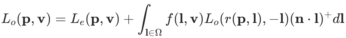
得到光源信息後,我將其與表面屬性傳給ShadeLighting進行光照計算,其內部使用了 PBR 模型進行計算,PBR 的材質模型使用 BSDF(雙向散射分佈函數)進行描述,該函數描述了在某個入射方向下,經過物體表面散射後出射光線在不同方向的散射的分佈規律。該函數描述了其有兩個函數組成,分別為 BRDF(雙向反射分佈函數)和 BTDF(雙向透射分佈函數),及完整的 BSDF 可通過以下公式描述。由於常見材質的透射分量較小,因此在實現通用材質模型時通常把 BTDF 忽略,保留 BRDF。
BRDF 包含了兩個分量,即漫反射分量與鏡面反射分量,因此完整的表面響應可以描述為以下方程f(v,l) = fd(v,l) + fr(v,l),而整個渲染過程可以描述為該函數在半球上對入射光線 l 的積分,即法線方向的半球上所有入射光線對出射方向的貢獻。
鏡面分量的 BRDF
在多數情況下, PBR 中的使用的 BRDF 都是基於微表面理論的,即在微觀層面下物體的表面並不是完全光滑的,而是由大量按照某種規則排列的*面碎片組成,如下圖所示:
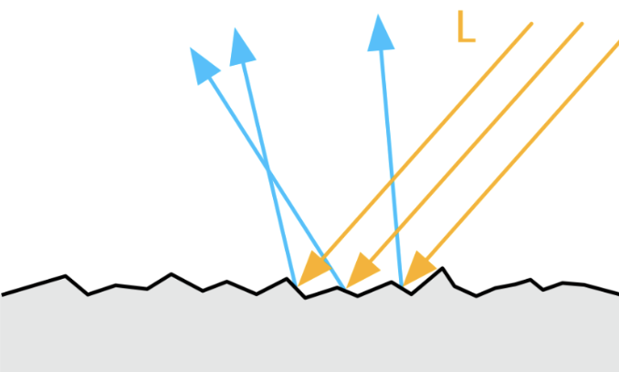
在微觀層面,物體的法線通常與宏觀層面有所不同,微表面的每一個*面碎片都有其自己的法線,因此在描述微表面的時候就需要引入一個函數來描述微觀層面的法線,而該函數就是法線分佈函數(Normal distribution function),通常使用 D 來表示。該函數受到微表面粗糙度的影響,微表面越粗糙,法線分佈越分散,沿着指定出射方向的出射的概率越小,反之則越大。但是即使是入射光線被微表面的法線正確的反射到了指定的出射方向上,該出射光線也不一定會對最終的結果造成貢獻,因為微表面還存在自遮擋和自陰影關係,如下圖所示:
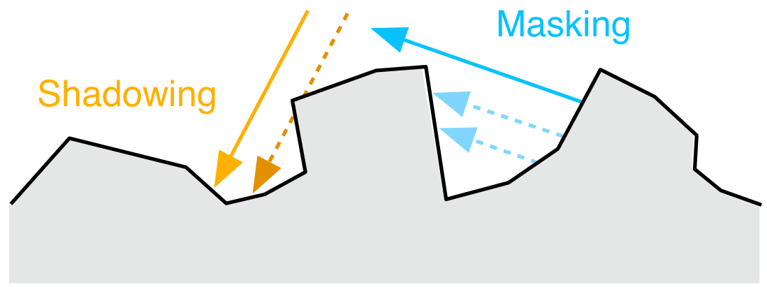
這時反射光線就不會對出射方向造成貢獻,因此還需要使用另外一個函數來擬合這種現象,幾何遮蔽函數(Geometric shadowing function)就應運而生了,通常使用 G 來表示該函數。除了這兩個基於微表面理論的函數,我們還需要考慮其他光線與物體表面交互的物理效應,當光與兩種物質之間的*面分界面發生相互作用時,會發生菲涅爾效應,也就是我們生活中遇到的當*乎*行觀察一個*面時,發生的反射效應會比垂直觀察時要強,該效應可以通過菲涅爾方程進行描述,通常使用 F 表示。
結合上面三個方程,我們就可以得到鏡面反射的 BRDF,數學形式如下:
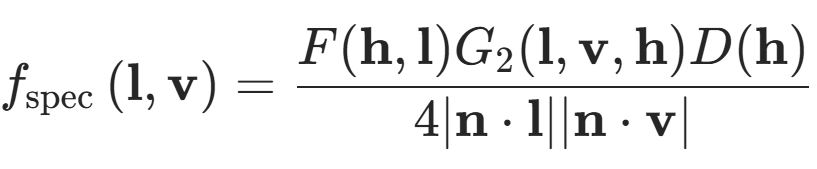
方程的分子就是上面提到的三個函數,而分子是歸一化常數。使用該函數對法線半球進行積分,就能得到完成的鏡面反射響應。PBR 經過多年的發展,有大量的模型來描述以上三個函數,這裏就介紹較為常用的模型。
首先是法線分佈函數,我使用的模型是 GGX 分佈,該分佈的衰減部分尾長較長,同時計算量也很適合實時渲染,因此在遊戲引擎中十分常用。該函數公式如下:
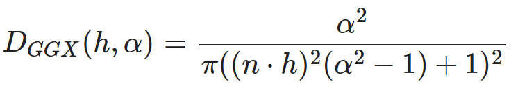
其中 α 為微表面的粗糙程度,n 為法線方向,h 為半程向量,也就是視線方向與光照方向的中間向量。具體實現如下:
// 使用 GGX 模型的法線分佈函數
// Dggx(h, r) =  r^2 / (pi * pow(pow(n * h, 2) * (r^2 - 1) + 1), 2)
float D_GGX(float NoH, float roughness)
{
    float a = roughness * roughness;
    float lower = lerp(1, a, NoH * NoH);    // 1 - (n * h)^2 + (n * h)^2 * r^2
    return a / max(1e-6, s_PI * lower * lower);  // 避免除零
}
這裏的 NoH 為法線點乘半程向量,第二行使用了內置函數lerp來計算分母,同時還需要避免除以零的情況。
幾何遮蔽函數的自變量為粗糙程度 α、入射方向 l 與出射方向 v,其又可以拆分為,兩個相同形式的函數的乘積,表達式如下:
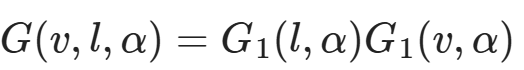
該函數同樣也有多種模型,這裏使用的為 GGX 模型,其公式為:
此時注意力驚人的朋友應該注意到了,完整的 G 的分母其實與鏡面反射的 BRDF 的分子約掉了,因此這裏為了減少計算量就將兩者合併計算了,因此具體實現如下:
// Smith 將幾何陰影函數分解為兩個函數的乘積
// G(v, l, r) = G1(l, r) * G1(v, r)
// 使用 GGX 模型的 G1 函數
// G1_GGX(v, r) = 2 * (n * v) / (n * v + sqrt(r^2 + (1 - r^2) * (n * v)^2))
// 結合上面鏡面反射的分母,可以化簡為函數 V(v, r)
// V_GGX(v, r) = 1 / ((n * v) + sqrt(r^2 + (1 - r^2) * (n * v)^2))
float V_SmithGGXCorrelated(float NoV, float NoL, float roughness)
{
    float a = roughness * roughness;
    float gv = NoL + sqrt(a + (1 - a) * NoV * NoV);
    float gl = NoV + sqrt(a + (1 - a) * NoL * NoL);
    return 1 / max(1e-6, gv * gl); // 避免除零
}
這裏的 NoL 為法線與光線方向的點乘。
最後便是菲涅爾方程,原始的菲涅爾方程特別複雜,因此通常使用施利克*似來實現其計算,公式如下:

其中 f0 為垂直入射時的反射光量,f90 為*行入射時的反射光量,通常為1,也就是完全反射。具體實現如下:
// 使用 Schlick *似的菲涅爾項
// F_Schlick(l, h, f0) = f0 + (1 - f0) * pow(1 - (l * h), 5)
float3 F_Schlick(float3 f0, float f90, float cos)
{
    return f0 + (f90 - f0) * pow(1 - cos, 5);
}

float F_Schlick(float f0, float f90, float cos)
{
    return f0 + (f90 - f0) * pow(1 - cos, 5);
}
這時又有如何決定 f0 和 f90 的問題了,f90 前面提到過通常為1,因此直接使用1即可,而 f0 的經過測量法線電解質的 f0 通常很小,而金屬的 f0 為其顏色,因此 f0 使用以下式子決定:
// 電介質的法線入射的亮度
static float3 s_DielectricSpecular = float3(0.04, 0.04, 0.04);

float3 f0 = lerp(s_DielectricSpecular, surface.color, surface.metallic);
最後鏡面反射分量的 BRDF 如下:
// 鏡面反射項
float3 SpecularBRDF(float NoV, float NoL, float NoH, float VoH, float3 f0, float roughness)
{
    float ND = D_GGX(NoH, roughness);
    float GV = V_SmithGGXCorrelated(NoV, NoL, roughness);
    float3 F = F_Schlick(f0, 1.0, VoH);
    return ND * GV * F;
}
漫反射分量的 BRDF
漫反射分量的 BRDF 同樣由多種模型,常用的 Lambertian 模型的 BRDF 假設半球上的漫反射響應都是均勻的,其公式為:
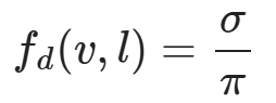
其中 σ 為漫反射率,也就是物體的顏色。而迪士尼漫反射模型將粗糙度考慮了進去,其公式為:

其將 f0 設置為了1,而 f90 的計算方式如下:
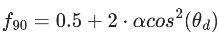
其實我也挺迷惑為何要這麼計算的。
最後漫反射分量的 BRDF 如下:
// 迪士尼漫反射項
float DiffuseBurley(float NoV, float NoL, float LoH, float roughness)
{
    float f90 = 0.5 + 2.0 * roughness * LoH * LoH;
    float lightScatter = F_Schlick(1.0, f90, NoL);
    float viewScatter = F_Schlick(1.0, f90, NoV);
    return lightScatter * viewScatter / s_PI;
}
最後將微表面模型的 BRDF 帶入渲染方程即可:
float3 ShadeLighting(Surface surface, Light light)
{
    float3 halfDir = normalize(light.direction + surface.viewDir);
    float NoV = saturate(dot(surface.normal, surface.viewDir));
    float NoL = saturate(dot(surface.normal, light.direction));
    float NoH = saturate(dot(surface.normal, halfDir));
    float LoH = saturate(dot(light.direction, halfDir));    // 與 VoH 相同

    float3 f0 = lerp(s_DielectricSpecular, surface.color, surface.metallic);
    float3 specular = SpecularBRDF(NoV, NoL, NoH, LoH, f0, surface.roughness);
    float3 diffuse = DiffuseBurley(NoV, NoL, LoH, surface.roughness);
    float3 diffuseCol = surface.color * (1 - surface.metallic);
    diffuse *= diffuseCol;

    float3 radians = NoL * light.color * (diffuse + specular);
    return radians * light.attenuation;
}
自此直接光照也算完全實現了,得到的結果如下:

間接光照的計算
在光柵化中,間接光照的計算十分複雜,通常使用 SSR、IBL、LightMap、SSAO 等技術實現,但是在光追中由於光線追蹤自生的全局性,因此實現更為簡單,只需要在着色點再次往四周 Trace 光線即可,如何高效的 Trace 這些光線才是真正的難點。
這裏沒有像常規的光追一樣生成隨機光線並 Trace 光線,而是隻沿着反射方向 Trace 光線,因此最後的結果是有偏的:
// 若表面很粗糙則不追蹤反射光線
[branch]
if(surface.roughness <= 0.99f) {
    // 獲得反射光線
    RayTracing::Ray reflectRay;
    reflectRay.origin = surface.position;
    reflectRay.direction = reflect(WorldRayDirection(), surface.normal);
    refColor = TraceRadianceRay(reflectRay, surface.recursionDepth);

    // 計算反射係數
    float3 f0 = lerp(s_DielectricSpecular, surface.color, surface.metallic);
    float cos = saturate(dot(surface.normal, surface.viewDir));
    float3 F = F_Schlick(f0, 1.0, cos);

    refColor.rgb *= F * (1 - roughness);
}
這裏通過計算菲涅爾項的反射係數來決定反射顏色的權重,最後疊加上反射顏色並寫入光追負載:
color += refColor.rgb;
payload.color = float4(color, surface.alpha);
Miss Shader
光照計算使用的 Miss Shader 十分簡單,直接返回了藍色:
[shader("miss")]
void MissShader(inout RayTracing::RayPayload payload)
{
    payload.color = float4(0.529, 0.808, 0.922, 1);
}
而陰影計算的 Miss Shader 則是將可見性改為 true:
// 若陰影光線不與物體相交則表示可見
[shader("miss")]
void MissShader_Shadow(inout RayTracing::ShadowRayPayload payload)
{
    payload.visible = true;
}
程序圖元的實現
程序圖元的實現需要使用先前都未使用過的 Intersection Shader,在調用TraceRay之後,光線會遍歷加速結構,若是遇到葉子節點,則會判斷是否是三角圖元,若不是三角形,則會在 Hit Group 的 Shader Table 查找其對應的 Intersection Shader,並調用,若是不存在則會繼續遍歷。由此可見我們需要添加的為程序圖元的 Hit Group、對應的加速結構以及對應的 Shader Record。
Intersection Shader
這裏先實現程序圖元的 Intersection Shader,目前暫時先實現了球、矩形和四邊形的 Intersection Shader。Shader 本體如下:
// Procedural Geometry Local
ConstantBuffer<RayTracing::PrimitiveInstanceConstantBuffer> lPrimitiveInstanceCB : register(b2);

[shader("intersection")]
void IntersectionShader_AnalyticPrimitive()
{
    Ray ray = {ObjectRayOrigin(), ObjectRayDirection()};
    RayTracing::AnalyticPrimitive::PrimitiveType primType = (RayTracing::AnalyticPrimitive::PrimitiveType)lPrimitiveInstanceCB.primitiveType;

    float time;
    RayTracing::ProceduralPrimitiveAttributes attrs = (RayTracing::ProceduralPrimitiveAttributes)0;
    if(RayAnalyticPrimitiveIntersectionTest(ray, primType, attrs, time)){
        ReportHit(time, 0, attrs);
    }
}
我沒有每個圖元都單獨實現一個 Intersection Shader,而是使用了常量緩衝區,內部儲存了當前圖元的類型,同時還構造了一根對象空間的光線,使用對象空間的原因是我們可以直接在 HLSL 中定義一個單位圖元,該圖元位於對象空間內,因此可以直接使用對象空間的光線進行相交檢測,省去了將圖元變換到世界空間的步驟。構造完光線之後,這裏調用了我實現的函數RayAnalyticPrimitiveIntersectionTest,其定義如下:
bool RayAnalyticPrimitiveIntersectionTest(
    in Ray ray,
    in AnalyticPrimitive::PrimitiveType primType,
    out ProceduralPrimitiveAttributes attrs,
    inout float time)
{
    switch(primType){
    case AnalyticPrimitive::PrimitiveType::Sphere:
        return RaySphereIntersectionTest(ray, attrs, time);
    case AnalyticPrimitive::PrimitiveType::Quad:
        return RayQuadIntersectionTest(ray, attrs, time);
    case AnalyticPrimitive::PrimitiveType::Cube:
        return RayCubeIntersectionTest(ray, attrs, time);
    default:
        return false;
    }
}
其會根據傳入的圖元類型調用對應的相交檢測,同時其還有兩個輸出參數attrs與time,分別為交點的幾何數據與光線起點到交點的距離。交點數據的定義如下:
struct ProceduralPrimitiveAttributes
{
    float3 normal;
    float2 uv;
    bool frontFace;
};
其中第三個參數表示了交點是物體的正面還是反面,根據該參數法線會對應的調整。在判斷完是否相交後,Intersection Shader 還調用了一個內置函數ReportHit,該函數的定義如下:
template<attr_t>
bool ReportHit(float THit, uint HitKind, attr_t Attributes);
傳入的第一個參數會決定該相交是否會被接受,接受的條件為 THit 在光線的區間內,也就是RayTMin和RayTCurrent,前面也提到過RayTCurrent在 Intersection Shader 中會返回當前最*的相交距離,若是 THit 在區間內,則會調用對應的 Any Hit Shader,沒有 Any Hit Shader 則會直接改變光線的區間的最遠值為 THit 並返回true。但是若是有 Any Hit Shader 且在內部調用了內置函數IgnoreHit,則當前提交會被是為失敗,且不會更新光線的區間,同時 false 表示該 HIt 未被接受。
判斷幾何體相交的具體實現這裏就不過多解釋了,具體的推導過程可以翻閲 RTR4 第22章對應的幾何體相交,或是 RayTracingInOneWeekend 的對應部分,這裏只放出代碼。球的相交檢測:
// 測試射線是否和球體相交
bool RaySphereIntersectionTest(
    in Ray ray,
    out ProceduralPrimitiveAttributes attrs,
    inout float time)
{
    // 在局部座標中的球心和半徑
    const float3 center = float3(0,0,0);
    const float radius = 1;

    float3 oc = center - ray.origin;
    float a = dot(ray.direction, ray.direction);
    float h = dot(ray.direction, oc);
    float c = dot(oc, oc) - radius * radius;
    float invA = 1.0f / a;

    float discriminant = h * h -  a * c;
    if (discriminant < 0) { // 沒有根則不相交
        return false;
    }
    float sqrtD = sqrt(discriminant);
    float root = (h - sqrtD) * invA;  // 計算方程的根
    if (root < RayTMin() || root > RayTCurrent()) { //不再範圍內
        root = (h + sqrtD) * invA;
        if (root < RayTMin() || root > RayTCurrent()) { //不再範圍內
            return false;
        }
    }

    float3 pos = ray.origin + root * ray.direction; // 計算交點
    float3 posWS = mul(float4(pos,1), ObjectToWorld4x3()).xyz; // 轉到世界空間
    float3 centerWS = mul(float4(center,1), ObjectToWorld4x3()).xyz;
    float3 normal = normalize(posWS - centerWS);

    float invPI = 1.f / s_PI;
    float theta = acos(normal.y);
    float phi = atan2(normal.z, normal.x);
    attrs.uv = float2((phi + s_PI) * 0.5f * invPI, theta * invPI);
    attrs.frontFace = dot(ray.direction, normal) < 0;
    attrs.normal = attrs.frontFace ? normal : -normal;

    time = root;

    return true;
}
正四邊形的檢測:
// 測試射線是否和四邊形相交
bool RayQuadIntersectionTest(
    in Ray ray,
    out ProceduralPrimitiveAttributes attrs,
    inout float time)
{
    // 單位四邊形的參數
    const float3 q = float3(-1, -1, 0);
    const float3 u = float3(2, 0, 0);
    const float3 v = float3(0, 2, 0);

    float3 w = float3(0, 0, 0.25f);
    float3 normal = float3(0, 0, 1);

    // 判斷射線是否與*面相交
    float nd = dot(normal, ray.direction);
    if(abs(nd) < 1e-4f)
        return false;

    // 計算交點
    time = -dot(normal, ray.origin) / nd;
    float3 pos = ray.origin + time * ray.direction; // 計算交點

    float3 pq = pos - q;
    float alpha = dot(w, cross(pq, v));
    float beta = dot(w, cross(u, pq));

    if(!InRange(alpha, 0, 1) || !InRange(beta, 0, 1))
        return false;

    // 將法線變換到世界空間
    normal = mul(normal, (float3x3)transpose(WorldToObject4x3()));
    attrs.uv = float2(alpha, beta);
    attrs.frontFace = nd < 0;
    attrs.normal = attrs.frontFace ? normal : -normal;

    return true;
}
矩形的相交檢測:
bool RayCubeIntersectionTest(in Ray ray, float3 boxMin, float3 boxMax, inout float time)
{
    float3 origin = ray.origin;
    float3 dir = ray.direction;

    // [min, max]
    const float3 invDir = 1.0f / dir;
    float3 t0 = (boxMin - origin) * invDir;
    float3 t1 = (boxMax - origin) * invDir;

    float2 interval = float2(RayTMin(), RayTCurrent());
    for (uint i = 0; i < 3; ++i) {
        const float tmin = (t0[i] < t1[i]) ? t0[i] : t1[i];
        const float tmax = (t0[i] < t1[i]) ? t1[i] : t0[i];

        if (tmin > interval.x) interval.x = tmin;
        if (tmax < interval.y) interval.y = tmax;

        if (interval.x >= interval.y) return false;
    }

    time = interval.x;
    return true;
}

bool RayCubeIntersectionTest(
    in Ray ray,
    out ProceduralPrimitiveAttributes attrs,
    inout float time)
{
    float3 boxMin = float3(-1,-1,-1);
    float3 boxMax = float3(1,1,1);

    if(!RayCubeIntersectionTest(ray, boxMin, boxMax, time)){
        return false;
    }

    float3 pos = ray.origin + time * ray.direction; // 計算交點

    float3 boxVec = pos / max(max(abs(pos.x), abs(pos.y)), abs(pos.z));
    float3 normal = float3(
        abs(boxVec.x) > 0.9999 ? sign(boxVec.x) : 0,
        abs(boxVec.y) > 0.9999 ? sign(boxVec.y) : 0,
        abs(boxVec.z) > 0.9999 ? sign(boxVec.z) : 0
    );

    // 將法線變換到世界空間
    normal = mul(normal, (float3x3)transpose(WorldToObject4x3()));
    attrs.uv = (pos.xy - boxMin.xy) * 0.5f;
    attrs.frontFace = dot(ray.direction, normal) < 0;
    attrs.normal = attrs.frontFace ? normal : -normal;

    return true;
}
創建加速結構
這裏我單獨實現了一個類來輔助程序圖元的創建,其實如下:
// 統一管理所有的程序圖元
class ProceduralGeometryManager
{
public:
    ProceduralGeometryManager();

    void AddGeometry(const ProceduralGeometryDesc& desc);

    const std::vector<ProceduralGeometry>& GetAllGeometry() const { return m_ProceduralGeometrys; }


private:
    // 底層加速結構
    std::array<AccelerationStructureBuffers, RayTracing::AnalyticPrimitive::Count> m_AnalyticPrimitives{};

    // 程序圖元實例數據
    std::vector<ProceduralGeometry> m_ProceduralGeometrys{};
    uint32_t m_InstanceContributionToHitGroupIndex = 0;
};
在該類構造函數中會創建所有圖元的底層加速結構,而每次添加幾何體時並不會增加底層加速結構,而是添加一個程序圖元的實例ProceduralGeometry,其實現如下:
struct ProceduralGeometry
{
    RayTracing::AnalyticPrimitive::PrimitiveType type;	// 圖元類型
    std::shared_ptr<Material> material;	// 材質
    D3D12_RAYTRACING_INSTANCE_DESC instanceDesc{};	// 實例
    uint32_t srvOffset = 0;	// 紋理在 Descriptor Heap 中的偏移
};
創建底層加速結構的具體過程這裏就不贅述了,這裏提一下在填寫D3D12_RAYTRACING_GEOMETRY_DESC需要指定的類型為 AABB 且填寫的數據為底層加速結構的 AABB,具體操作如下:
D3D12_RAYTRACING_AABB aabb{
    .MinX = -1.0f, .MinY = -1.0f, .MinZ = -1.0f,
    .MaxX =  1.0f, .MaxY =  1.0f, .MaxZ =  1.0f
};
D3D12_RAYTRACING_GEOMETRY_AABBS_DESC aabbDesc{};
aabbDesc.AABBCount = static_cast<UINT>(aabb.size());
aabbDesc.AABBs.StartAddress = aabbBuffer.GetGpuVirtualAddress();
aabbDesc.AABBs.StrideInBytes = sizeof(D3D12_RAYTRACING_AABB);
D3D12_RAYTRACING_GEOMETRY_DESC geometryDesc{};
geometryDesc.Type = D3D12_RAYTRACING_GEOMETRY_TYPE_PROCEDURAL_PRIMITIVE_AABBS;
geometryDesc.Flags = D3D12_RAYTRACING_GEOMETRY_FLAG_OPAQUE;
geometryDesc.AABBs = std::move(aabbDesc);
這裏需要注意的是填寫 AABB 時需要是對象空間下的 AABB,不需要進行變換,因為光線在遍歷加速結構時是出於對象空間中,同時也需要保證該 AABB 能完全包圍程序圖元,不然會渲染錯誤。
在創建圖元的時候需要填寫對應的描述結構體,並調用AddGeometry,描述結構體具體如下:
struct ProceduralGeometryDesc
{
    RayTracing::AnalyticPrimitive::PrimitiveType type;	// 圖元類型
    Transform transform;	// 幾何變換
    std::shared_ptr<Material> material;	// 材質
    std::array<TextureRef, kNumTextures> textures;	// 使用的紋理
};
隨後就會創建對應的實例並插入數組中,具體操作如下:
void ProceduralGeometryManager::AddGeometry(const ProceduralGeometryDesc &desc)
{
    auto createInstance = [this, &desc](auto primitiveType){
        assert(desc.material != nullptr);

        const auto& sphereBottomLevelAS = m_AnalyticPrimitives[primitiveType].accelerationStructure;
        D3D12_RAYTRACING_INSTANCE_DESC instanceDesc{};
        instanceDesc.InstanceID = static_cast<UINT>(m_ProceduralGeometrys.size());
        instanceDesc.InstanceMask = RayTracing::TraceRayParameters::InstanceMark;
        instanceDesc.Flags = D3D12_RAYTRACING_INSTANCE_FLAG_FORCE_OPAQUE;
        instanceDesc.InstanceContributionToHitGroupIndex = m_InstanceContributionToHitGroupIndex;
        instanceDesc.AccelerationStructure = sphereBottomLevelAS.GetGpuVirtualAddress();
        DirectX::XMStoreFloat3x4(&reinterpret_cast<DirectX::XMFLOAT3X4&>(instanceDesc.Transform), desc.transform.GetLocalToWorld());
        if(desc.type == RayTracing::AnalyticPrimitive::Quad){
            instanceDesc.Transform[2][2] = 1;
        }

        D3D12_CPU_DESCRIPTOR_HANDLE defaultTexture[kNumTextures] = {
            Graphics::GetDefaultTexture(Graphics::kWhiteOpaque2D),
            Graphics::GetDefaultTexture(Graphics::kWhiteOpaque2D),
            Graphics::GetDefaultTexture(Graphics::kWhiteOpaque2D),
            Graphics::GetDefaultTexture(Graphics::kWhiteOpaque2D),
            Graphics::GetDefaultTexture(Graphics::kBlackTransparent2D),
            Graphics::GetDefaultTexture(Graphics::kDefaultNormalTex)
        };
        for(int i = 0; i < desc.textures.size(); ++i){
            if(desc.textures[i].IsValid()){
                defaultTexture[i] = desc.textures[i].GetSRV();
            }
        }
        DescriptorHandle texHandle = g_Renderer.m_TextureHeap.Allocate(kNumTextures);

        std::uint32_t destCount = kNumTextures;
        std::uint32_t srcCount[kNumTextures] = {1,1,1,1,1,1};
        g_RenderContext.GetDevice()->CopyDescriptors(
            1, &texHandle, &destCount, destCount, defaultTexture, srcCount, D3D12_DESCRIPTOR_HEAP_TYPE_CBV_SRV_UAV);

        GpuBufferDesc materialBufferDesc{};
        materialBufferDesc.m_Size = sizeof(MaterialConstantBuffer);
        materialBufferDesc.m_Stride = sizeof(MaterialConstantBuffer);
        ProceduralGeometry geometry{};
        geometry.type = desc.type;
        geometry.material = desc.material;
        geometry.instanceDesc = std::move(instanceDesc);
        geometry.srvOffset = g_Renderer.m_TextureHeap.GetOffsetOfHandle(texHandle);
        m_ProceduralGeometrys.push_back(std::move(geometry));
        m_InstanceContributionToHitGroupIndex += RayTracing::RayType::Count;
    };

    switch (desc.type) {
        case RayTracing::AnalyticPrimitive::Sphere:
            createInstance(RayTracing::AnalyticPrimitive::Sphere); break;
        case RayTracing::AnalyticPrimitive::Quad:
            createInstance(RayTracing::AnalyticPrimitive::Quad); break;
        case RayTracing::AnalyticPrimitive::Cube:
            createInstance(RayTracing::AnalyticPrimitive::Cube); break;
        default:
            break;
    }
}
有了這個輔助類,在創建加速結構的時候也方便了許多,只需要直接將實例D3D12_RAYTRACING_INSTANCE_DESC插入數組即可:
// 添加程序圖元的實例
for(const auto& geometry : m_ProceduralGeometryManager->GetAllGeometry()){
    auto instanceDesc = geometry.instanceDesc;
    instanceDesc.InstanceContributionToHitGroupIndex += instanceContributionToHitGroupIndex;
    instanceDescs.push_back(std::move(instanceDesc));
}
注意這裏的在 Shader Table 中的偏移需要加上全部三角圖元的偏移,因為他們共用同一個 Shader Table。
添加 Shader Record
在 Hit Group 的 Shader Table 中,還需要為程序圖元額外添加 Shader Record,由於兩種圖元都共用一個 Miss Shader 因此,Miss Shader Table 就不需要添加了。具體的流程也是獲取 Hit Group 其對應的着色器標識,然後填寫 Shader Record 中的根參數:
... // 三角圖元的 Shader Identifier

std::array<void*, RayTracing::RayType::Count> hitGroupIdentifiersAABB{};
for (size_t i = 0; i < RayTracing::RayType::Count; i++) {
    hitGroupIdentifiersAABB[i] = stateObjectProps->GetShaderIdentifier(Renderer::s_HitGroupName_AABB[i]);
}

... // 三角圖元的 Shader Record
for(const auto& geometry : m_ProceduralGeometryManager->GetAllGeometry()){
    for(int i = 0; i < RayTracing::RayType::Count; ++i){
        hitGroupShaderRecordData.clear();
        hitGroupShaderRecordData.resize(hitGroupShaderRecordSize, 0);
        memcpy(hitGroupShaderRecordData.data(), hitGroupIdentifiersAABB[i], shaderIdSize);
        if(i == RayTracing::RayType::Radiance){
            LocalRootSignature::AABB::RootArguments rootArgs{};
            rootArgs.primitiveInstance.primitiveType = geometry.type;
            rootArgs.material.baseColor = geometry.material->baseColor;
            rootArgs.material.emissiveColor = geometry.material->emissiveColor;
            rootArgs.material.roughnessFactor = geometry.material->roughnessFactor;
            rootArgs.material.metallicFactor = geometry.material->metallicFactor;
            rootArgs.material.normalTexScale = geometry.material->normalTexScale;
            rootArgs.textures = g_Renderer.m_TextureHeap[geometry.srvOffset];
            memcpy(hitGroupShaderRecordData.data() + shaderIdSize, &rootArgs, sizeof(rootArgs));
        }
        hitGroupShaderTableData.append_range(hitGroupShaderRecordData);
    }
}
在創建 PSO 的時候還需要為程序圖元創建對應的 Hit Group:
std::array<D3D12_HIT_GROUP_DESC, RayTracing::RayType::Count> hitGroupDescsAABB{};
for (int i = 0; i < RayTracing::RayType::Count; ++i) {
    auto& hitGroupDesc = hitGroupDescsAABB[i];
    hitGroupDesc.Type = D3D12_HIT_GROUP_TYPE_PROCEDURAL_PRIMITIVE;
    hitGroupDesc.HitGroupExport = s_HitGroupName_AABB[i];
    if(i == RayTracing::RayType::Radiance){
        hitGroupDesc.ClosestHitShaderImport = s_ClosestHitShaderName[GeometryType::AABB];
    }
    hitGroupDesc.IntersectionShaderImport = s_IntersectionShaderName[IntersectionShaderType::AnalyticPrimitive];

    D3D12_STATE_SUBOBJECT hitGroupSubobject{};
    hitGroupSubobject.Type = D3D12_STATE_SUBOBJECT_TYPE_HIT_GROUP;
    hitGroupSubobject.pDesc = &hitGroupDesc;
    subobjects.push_back(std::move(hitGroupSubobject));
}
程序圖元的 Closest Hit Shader 與三角形基本一樣,只有獲取法線、紋理座標不一樣,這裏就不贅述了。最後得到的輸出如下:

可以看到反射分量有點突兀,應為僅僅採樣了反射方向的間接光照,這裏使用的最大遞歸深度只有3,若是提高遞歸深度,還能得到更多的細節:

這裏將遞歸深度提高到了6,可以很明顯的看到球和四邊形那裏反射除了額外的東西。
詳細代碼可見我的GitHub:https://github.com/wsdanshenmiao/LearnMiniEngine
